A greenhouse supplier may receive an inquiry that states:
Understanding greenhouse snow load is crucial for ensuring structural integrity in colder climates.
- Snow load: 1.5 kN/m²
- Greenhouse snow load calculations are essential.
- Wind speed: 35 m/s
- Greenhouse width: 6 m
- Assessing greenhouse snow load is vital for safety.
- Required structure: heavy-duty galvanized steel
These figures are important, but they are not a complete structural specification.
Calculating greenhouse snow load must consider various factors.
A snow-load value does not directly determine one pipe size. A wind-speed value does not represent the final pressure acting on every roof, wall, fixing, connection and foundation. Before these environmental inputs can become a reliable commercial greenhouse structure, they must be translated into load cases, frame spacing, member arrangements, bracing systems, connection forces, covering fixings and foundation reactions.
Greenhouse snow load varies based on design and location.
This is why a meaningful greenhouse structural review must look beyond the main arch.
A load rating is not a material specification.
Evaluating greenhouse snow load is critical for architects.
The real question is whether the stated snow and wind requirements have been converted into a complete and traceable load path.
Important Scope Note
Understanding the impact of greenhouse snow load is essential.
This article explains engineering awareness, preliminary supplier-side review logic and RFQ preparation for commercial greenhouse projects.
It is not a project-specific structural calculation, local code approval, stamped drawing or substitute for verification by a qualified structural engineer.
Final structural verification must consider the applicable local code, project location, terrain, exposure, greenhouse geometry, covering system, openings, foundation conditions, installation method and approval requirements.
What Is Greenhouse Snow Load?
Greenhouse snow load is the structural action created by snow accumulating on the greenhouse roof.
The greenhouse snow load must be accurately assessed.
It is normally expressed as a pressure, such as:
- 0.75 kN/m²
- Greenhouse snow load varies regionally.
- 1.0 kN/m²
- 1.5 kN/m²
- 2.0 kN/m²
However, the snow load acting on a greenhouse roof is not determined only by how much snow falls in the region.
Experts recommend calculating greenhouse snow load carefully.
It may also be affected by:
- characteristic ground snow load;
- roof shape and slope;
- arch curvature;
- exposure to winter wind;
- nearby buildings or higher roofs;
- roof covering material;
- heat transmission through the covering;
- Proper design must consider greenhouse snow load.
- internal temperature;
- snow sliding;
- snow drifting;
- melting and refreezing;
- local design codes and national annexes.
Ground Snow Load vs Roof Snow Load
Understanding greenhouse snow load is vital for structural integrity.
One of the first questions in a greenhouse RFQ should be:
Does the stated value represent ground snow load or roof snow load?
Ground snow load describes the characteristic weight of snow accumulated on the ground for a defined location and reference period.
Roof snow load is the structural load assigned to the roof after considering the applicable roof shape, exposure, thermal and redistribution rules.
The two values are not automatically the same.
If a customer states only “snow load: 1.5 kN/m²,” the supplier and project engineer should confirm:
- whether it is a ground or roof value;
- whether it is characteristic or factored;
- whether it applies to the horizontal roof projection;
- which code or authority supplied the value;
- whether uniform, partial, drifted and unbalanced cases are included.
A ground snow-load value should not be applied directly to the greenhouse roof without the required conversion under the applicable code.
Characteristic Load vs Design Load
A greenhouse project may refer to several different types of load value:
- Greenhouse snow load impacts overall design.
- meteorological ground snow data;
- characteristic ground snow load;
- characteristic roof snow load;
- specified project snow-load target;
- unfactored structural action;
- factored design action;
- governing load combination.
These values should not be mixed.
Design and structural analysis should include greenhouse snow load.
For example, the characteristic roof snow load used to explain a preliminary frame arrangement may not be the same value used in a final ultimate limit state calculation.
The design basis should clearly identify which type of value has been supplied.
What Is Greenhouse Wind Load?
Greenhouse snow load must be examined thoroughly for safety.
Greenhouse wind load is the combination of external pressure, suction and internal pressure acting on the greenhouse envelope and transferring into the structural frame and foundations.
Wind is not only a horizontal force pushing against one side of the greenhouse.
Depending on wind direction, greenhouse geometry and enclosure condition, wind may create:
- positive pressure on the windward wall;
- Ignoring greenhouse snow load can lead to failure.
- suction on the leeward wall;
- suction on roof surfaces;
- pressure on end walls;
- high localized suction at edges and corners;
- internal pressure through doors, vents or damaged covering;
- sliding and overturning forces;
- uplift at anchors and foundations.
This means greenhouse wind resistance depends on the whole envelope-to-foundation system.
Wind resistance is not determined by the main frame alone.
The covering, locking profiles, fasteners, purlins, bracing, end-wall framing, base connections, anchors and foundations all participate in the wind load path.
For a more detailed discussion of openings, internal pressure and uplift, see How Wind Load Affects Commercial Greenhouse Structure Design.
Why a Snow-Load Number Alone Is Not Enough
A value such as 1.5 kN/m² is an important input, but it does not define the final greenhouse structure.
Each greenhouse’s snow load requirements differ based on various factors.
Two greenhouses designed for the same nominal snow load may require different arrangements because they have different:
- widths;
- heights;
- roof shapes;
- Greenhouse snow load should be factored into all designs.
- arch spacing;
- covering systems;
- purlin layouts;
- end-wall configurations;
Reviewing the greenhouse snow load is essential before construction.
- bracing systems;
- foundation conditions;
- heating assumptions.
A 6 m single-span arch greenhouse behaves differently from a large commercial multi-span greenhouse structure.
Understanding the greenhouse snow load helps in planning.
A pointed Gothic greenhouse has a different roof geometry and snow-shedding behavior from a rounded arch.
A rigid polycarbonate greenhouse structure also has different covering weight, fixing details and load-transfer interfaces from a single-layer film greenhouse.
The snow-load number must therefore be evaluated together with the actual greenhouse system.
Exposure, Roof Shape and Thermal Conditions
Ensure the greenhouse snow load is properly calculated for efficiency.
An exposed agricultural site may experience stronger winter winds and greater snow redistribution than a sheltered site.
Roof geometry affects whether snow:
- remains relatively balanced;
- accumulates on one side;
- Assessing greenhouse snow load is crucial in design.
- slides toward gutters;
- drifts near roof transitions;
- concentrates against an obstruction;
- moves from an upper roof to a lower roof.
Architects must consider the greenhouse snow load in their designs.
Thermal conditions may also affect snow accumulation, but heat-related reductions cannot be assumed merely because the greenhouse has a heating system.
Why Controlled Heating Cannot Be Assumed
A customer may expect greenhouse heating to melt snow and reduce the required structural snow load.
This assumption is only reasonable when the snow-melting function is deliberate, measurable and reliable under the design event.
Greenhouse snow load is a key component in structural evaluations.
Relevant questions include:
- What minimum air temperature is maintained below the roof?
- Can that temperature be maintained throughout heavy snowfall?
- Is the roof covering sufficiently heat-transmissive?
Verify the greenhouse snow load in final designs for safety.
- Are thermal screens opened during snow-melting operation?
- Are roof vents and other openings closed?
- Is meltwater drainage adequate?
- Is there automatic backup heating?
Calculations regarding greenhouse snow load enhance safety.
- Is emergency electrical power available?
- Is there an alarm and monitoring system?
- What happens during fuel interruption or equipment failure?
EN 13031-2:2024 applies specifically to greenhouses open to the public and includes provisions for controlled snow loads on transparent cladding. Its requirements illustrate an important principle: snow-load reduction based on heating requires a dependable operating and safety system.
Confirm the greenhouse snow load before project approval.
For an ordinary commercial production greenhouse, whether heating can reduce the design snow load must still be determined under the applicable project code and confirmed by the responsible engineer.
Where no reliable controlled snow-melting system has been confirmed, the preliminary structural review should not assume that heating will remove the governing snow accumulation.
Why Uniform Snow Load Is Only One Design Case
Grasping greenhouse snow load impacts overall project safety.
Uniform or balanced snow load is often the easiest condition to understand. It assumes that snow is distributed relatively evenly over the roof.
But it is only one possible condition.
A greenhouse roof may also experience:
- unbalanced snow;
- Understanding greenhouse snow load is crucial for engineers.
- partial snow loading;
- snow drift;
- snow sliding;
- redistribution by wind;
Thorough understanding of greenhouse snow load can prevent issues.
- local accumulation near gutters or obstructions;
- melting on one roof area but not another;
- refreezing of meltwater.
Uniform snow load is only one load case.
Emphasizing greenhouse snow load is crucial in design discussions.
Balanced Snow Load
Balanced loading places snow across both sides of a symmetrical roof.
Under this condition, a well-proportioned arch may transfer a significant part of the load through compression and relatively symmetrical frame action.
However, balanced loading should not be treated as proof that the same structure will perform equally well under partial or one-sided loading.
Reviewing greenhouse snow load can prevent future failures.
Unbalanced or Partial Snow Load
Unbalanced loading may occur when:
- snow slides from one side first;
- one side receives more solar radiation;
Every architect should understand greenhouse snow load’s significance.
- wind removes snow from the windward side;
- snow drifts onto the leeward side;
- part of the greenhouse is heated more effectively;
- snow is manually removed from only part of the roof.
Calculate greenhouse snow load to avoid structural issues.
This changes the internal force pattern.
The structure may experience increased:
- bending;
- lateral displacement;
- Construction teams must understand greenhouse snow load calculations.
- asymmetric compression;
- connection demand;
- arch-foot movement;
- bracing force.
Greenhouse snow load should be assessed regularly for safety.
Snow Drift, Sliding and Redistribution
On multi-span and gutter-connected greenhouses, snow may slide or drift toward valley and gutter zones.
Nearby buildings, height changes and roof obstructions may also create local accumulation areas.
These local effects may govern a specific:
Understanding greenhouse snow load is key for project success.
- gutter;
- purlin;
- arch segment;
- connector;
Greenhouse snow load analysis is crucial for building safety.
- lower roof area;
- end bay.
An overall average snow load does not automatically capture these local demands.
Why Arch Roofs Are Sensitive to One-Sided Snow
Assessing greenhouse snow load is a critical design step.
Arch structures can be structurally efficient under suitable loading and restraint conditions.
However, their behavior is sensitive to load distribution.
A relatively symmetrical snow load may allow the arch to carry more of the action through compression. When the load becomes one-sided, the arch can develop larger bending moments and asymmetric deformation.
This is why a heavy-snow arch greenhouse should not be evaluated only by checking whether one tube can carry a uniformly distributed vertical load.
Greenhouse snow load should be included in final reviews.
The review should also consider:
- one-sided snow;
- partial unloading;
- lateral restraint;
- Understanding greenhouse snow load can guide structural design.
- arch-foot fixity;
- purlin interaction;
- tie members;
- truss action;
Regular reviews of greenhouse snow load can prevent failures.
- longitudinal bracing;
- connection stiffness.
How Arch Spacing Changes the Load on Each Frame
Greenhouse snow load assessments guide the engineering process.
Arch spacing directly affects the tributary area assigned to each frame.
For a simplified single-span greenhouse:
Tributary area per arch = Greenhouse width × Arch spacing
The simplified snow action associated with a typical interior arch can then be expressed as:
Understanding greenhouse snow load is crucial for structural integrity.
Snow load per arch = Tributary area × Specified roof snow load
This explains why reducing arch spacing can reduce the load assigned to each individual frame.
However, closer spacing does not automatically verify the greenhouse structure.
Performance still depends on:
Each design phase must account for greenhouse snow load.
- arch section properties;
- wall thickness;
- steel grade;
- buckling resistance;
Ensure greenhouse snow load calculations are precise.
- purlin and bracing arrangement;
- connection design;
- arch-foot restraint;
- foundation capacity;
- Document all aspects of greenhouse snow load in design reviews.
- governing load combinations.
Closer arch spacing reduces the tributary area per frame, but spacing alone does not verify structural safety.
Project Example: Cold-Climate Arch Greenhouse
Greenhouse snow load needs comprehensive understanding for safety.
Consider the following anonymous project example.
- Greenhouse snow load must be factored into planning stages.
Accurate greenhouse snow load calculations are paramount.Understanding greenhouse snow load is vital for long-term safety.Assessing greenhouse snow load should be part of routine checks.Greenhouse snow load needs to be monitored throughout its lifecycle.Thorough analysis of greenhouse snow load is essential for success.
| Project parameter | Value |
|---|---|
| Greenhouse width | 6 m |
| Greenhouse length | 30 m |
| Side height | 2.1 m |
| Peak height | 3.5 m |
| Arch spacing | 0.6 m |
| Horizontal roof projection | 180 m² |
| Specified snow load | 1.5 kN/m² |
| Target wind speed | 35 m/s |
| Covering | Single-layer film |
| Climate | Cold, snowy, windy and humid |
| Controlled snow-melting system | Not confirmed |
Calculation Boundary
This is a simplified illustrative calculation, not a formal structural verification.
For this example, the stated 1.5 kN/m² is treated as a specified characteristic roof snow load applied to the horizontal projected area.
Incorporating greenhouse snow load considerations can enhance safety.
If the stated value is actually a ground snow load, it cannot be transferred directly to the greenhouse roof without the applicable shape, exposure, thermal and code factors.
No load factors, combination factors, member checks, stability calculations or foundation calculations are applied in this example.
Whole-Greenhouse Snow-Load Magnitude
The horizontal projected roof area is:
Knowledge of greenhouse snow load is crucial for all stakeholders.
[6\text{ m} \times 30\text{ m} = 180\text{ m}²
]
The illustrative characteristic snow-load magnitude is:
[180\text{ m}² \times 1.5\text{ kN/m}² = 270\text{ kN}
]
A force of 270 kN is approximately equivalent to:
Addressing greenhouse snow load is essential for structural integrity.
[270 / 9.81 \approx 27.5\text{ tonnes-force}
]
Therefore, the whole greenhouse is associated with an illustrative snow-load magnitude of approximately:
270 kN, equivalent to about 27.5 tonnes-force distributed over the horizontal roof projection.
This does not mean that the total load acts at one location. It is distributed through the roof and structural system.
Evaluating greenhouse snow load can safeguard against structural failures.
Tributary Area per Typical Arch
For a typical interior arch with 0.6 m spacing:
[6\text{ m} \times 0.6\text{ m} = 3.6\text{ m}²
]
Illustrative Snow Load per Arch
Regular evaluations of greenhouse snow load can prevent disasters.
[3.6\text{ m}² \times 1.5\text{ kN/m}² = 5.4\text{ kN}
]
A force of 5.4 kN is approximately equivalent to:
[5.4 / 9.81 \approx 550\text{ kgf}
]
The result may be described as an illustrative characteristic snow-load magnitude of approximately 5.4 kN, or about 550 kgf, associated with the tributary area of a typical interior arch.
Greenhouse snow load should be framed as an essential design parameter.
It should not be interpreted as “one arch pipe only needs to carry 550 kg.”
The load must move through a complete system:
Snow load → covering system → purlins and main arches → tie or truss members → bracing → arch feet → anchors and foundations
Simplified Wind Velocity Pressure
Assessing greenhouse snow load is a vital practice for safety.
A basic physical approximation for velocity pressure is:
[q \approx 0.613V²
]
where:
- (q) is in N/m²;
Thorough evaluations of greenhouse snow load enhance project reliability.
- (V) is in m/s.
For a wind speed of 35 m/s:
[q \approx 0.613 \times 35²
] [
q \approx 751\text{ N/m}²
]
Greenhouse snow load is a vital consideration in effective design.
[q \approx 0.75\text{ kN/m}²
]
This is only a simplified base velocity pressure.
It is not the final design pressure on the greenhouse roof, walls, covering system or foundations.
Final wind actions may depend on:
Confirming greenhouse snow load is necessary for project approval.
- the definition of the stated wind speed;
- averaging period and gust basis;
- return period;
- terrain category;
Understanding greenhouse snow load is crucial to minimizing risks.
- exposure;
- site altitude;
- greenhouse height;
- roof geometry;
Every project must consider greenhouse snow load for optimal safety.
- wind direction;
- external pressure coefficients;
- internal pressure;
- edge and corner zones;
- Greenhouse snow load assessments are critical for structural reliability.
- end-wall conditions;
- openings and covering damage;
- local load combinations.
What This Example Proves
Proper analysis of greenhouse snow load is key to success.
The simplified example demonstrates that:
- a moderate-sized greenhouse can be associated with a large total snow-load magnitude;
- arch spacing directly changes the tributary area of each frame;
- wind speed must be converted into pressure before structural evaluation;
Greenhouse snow load evaluations must be thorough and consistent.
- the resulting pressure still requires surface coefficients and project-specific adjustments;
- the main arch cannot be evaluated in isolation.
What This Example Does Not Prove
The example does not prove that:
- a specific round tube satisfies the load;
- a specific oval tube satisfies the load;
- 0.6 m spacing is automatically adequate;
- a certain anchor is sufficient;
- the greenhouse complies with a Russian, European or other local code;
- the structure has been formally engineered or certified.
Why Wind Resistance Is More Than Frame Strength
Wind resistance is sometimes reduced to one question:
Will the steel frame bend?
That question is incomplete.
A commercial greenhouse may experience failures in:
- film locking channels;
- glazing retention systems;
- local fasteners;
- purlin connections;
- end-wall framing;
- ventilation openings;
- diagonal bracing;
- base plates;
- ground anchors;
- concrete foundations.
A stronger main arch cannot compensate for a broken load path.
Wind Speed Is Not Surface Pressure
Wind speed is converted into a reference velocity pressure, but the full pressure does not act equally on all greenhouse surfaces.
The University of Connecticut Extension provides an illustrative U.S. example for a 30 ft × 100 ft freestanding glass greenhouse under a stated set of height, exposure and wind assumptions.
| Surface in the UConn example | Illustrative pressure |
|---|---|
| Windward vertical sidewall | +14.9 psf, approximately +0.71 kPa |
| Windward-facing roof | −7.3 psf, approximately −0.35 kPa |
| Leeward-facing roof | −14.0 psf, approximately −0.67 kPa |
| Leeward wall | −5.6 psf, approximately −0.27 kPa |
For a similarly sized freestanding hoophouse, the same publication gives different illustrative values:
| Surface in the UConn hoophouse example | Illustrative pressure |
|---|---|
| Lower windward side | +11.2 psf, approximately +0.54 kPa |
| Upper half of roof | −5.1 psf, approximately −0.24 kPa |
| Lower leeward side | −9.4 psf, approximately −0.45 kPa |
These values should not be transferred to another greenhouse project.
They are useful because they demonstrate that:
- one wind event can create positive pressure on one surface and suction on another;
- greenhouse shape changes the pressure distribution;
- the roof may experience uplift rather than downward pressure;
- every surface and supporting component must be evaluated according to its own design condition.
Pressure Becomes Force When Applied Over an Area
The total force acting on a greenhouse surface depends on both pressure and loaded area:
[F = p \times A
]
where:
- (F) is the resulting force;
- (p) is surface pressure;
- (A) is the loaded area.
Even a moderate pressure can generate a large total force when applied over a long sidewall, roof block or end wall.
That total force must be transferred through:
- cladding;
- fixing profiles;
- local secondary members;
- main frames;
- bracing lines;
- base connections;
- foundations.
Positive Pressure and Roof Suction
The windward wall generally receives positive pressure.
At the same time, wind flowing over the roof may create negative pressure or suction.
This means the roof covering and its fixing system may be pulled outward or upward, rather than pushed downward.
For film greenhouses, the review may need to consider:
- film locking channels;
- spring wire;
- film overlap;
- end-wall fixing;
- anti-flap details;
- local reinforcement;
- continuity of the fixing system.
For rigid covering systems, the review may include:
- glazing bars;
- polycarbonate fasteners;
- panel edge support;
- washer and screw spacing;
- panel movement allowance;
- local edge and corner fixation.
Internal Pressure from Openings or Cover Damage
Doors, vents, roll-up sides, louvers and damaged covering can change the internal pressure condition.
If a large windward opening allows air to enter the greenhouse, internal pressure may increase.
When positive internal pressure pushes upward while external roof suction also acts upward, the two effects may combine.
This can increase demand on:
- roof covering;
- fixing profiles;
- purlin connections;
- frame joints;
- arch feet;
- anchor systems.
Operating assumptions therefore form part of the structural design basis.
If a greenhouse is designed on the assumption that doors and vents remain closed during a design wind event, the project must provide a reliable way to achieve that condition.
End-Wall and Edge-Zone Loads
The end wall should not be treated as a non-structural enclosure added after the main frame has been selected.
It may receive substantial pressure and may contain:
- large doors;
- fan openings;
- cooling-pad openings;
- service penetrations;
- ventilation equipment;
- local framing discontinuities.
Roof edges and corners may also experience higher localized suction than central roof areas.
The main frame, end-wall frame and covering fixation should therefore be coordinated as one system.
Foundation Uplift and Anchor Resistance
Wind actions eventually reach the foundation.
Depending on the load case, the foundation may need to resist:
- uplift;
- horizontal shear;
- overturning;
- sliding;
- combined tension and shear;
- local soil failure.
Foundation resistance depends on:
- soil type;
- groundwater;
- frost depth;
- anchor geometry;
- embedment depth;
- concrete dimensions;
- base-plate details;
- installation quality;
- corrosion protection.
Stronger arches cannot compensate for weak foundations or incompatible connectors.
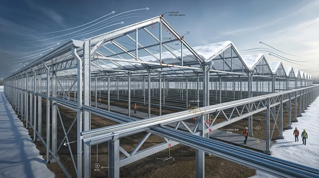
What Creates a Reliable Greenhouse Load Path?
A load path is the continuous route through which an environmental action moves from the surface of the greenhouse into the ground.
Snow Load Path
Snow → covering → purlins and arches → truss or tie system → bracing and frame feet → anchors and foundations
Wind Load Path
Wind pressure and suction → covering and end walls → fixing system → purlins and main frames → bracing → anchors and foundations
Every transition must be capable of transferring the required force.
Covering and Fixing System
The covering is normally the first structural interface affected by wind and snow.
It must transfer distributed pressure into the supporting members without premature:
- pull-out;
- tearing;
- panel disengagement;
- local buckling;
- excessive movement;
- fastener failure.
Main Arches, Columns and Purlins
Main arches or rafters carry transverse actions.
Purlins help support the covering, distribute local loads and connect repeated frames longitudinally.
Columns and arch feet transfer the accumulated actions toward the foundation.
Their performance depends not only on strength, but also on:
- unsupported length;
- buckling restraint;
- connection stiffness;
- section orientation;
- frame geometry;
- deformation limits.
Tie Beams, Bottom Chords and Web Members
Tie beams can help control the outward movement of arch feet.
Bottom chords and web members may create truss action and reduce bending demand in the main arch.
However, additional tubes do not automatically form an efficient truss.
The web-member arrangement, connection points and force directions must create a rational triangulated system.
Longitudinal and Diagonal Bracing
Repeated arches do not automatically create longitudinal stability.
Bracing may be required to:
- transfer end-wall wind loads;
- stabilize frame lines;
- prevent progressive racking;
- control installation geometry;
- restrain compression members;
- transfer actions into defined foundation locations.
Connections and Fasteners
A member can only transfer the force that its connections are capable of receiving.
Connection review may include:
- bolt diameter and grade;
- number and spacing of fasteners;
- clamp geometry;
- gusset plates;
- local bearing;
- tear-out;
- hole weakening;
- slip;
- weld capacity;
- installation tolerance;
- corrosion compatibility.
Anchors and Foundations
The load path is incomplete until the structural reactions have been transferred safely into the ground.
Foundation design may need to address:
- vertical compression;
- uplift;
- horizontal shear;
- overturning;
- frost action;
- drainage;
- soil variability;
- installation tolerance.
Does More Steel Automatically Mean a Stronger Greenhouse?
No.
More steel does not automatically mean a safer greenhouse.
Extra material may improve performance when it is placed in the correct location and connected through a clear load path.
But random reinforcement can also create:
- unnecessary weight;
- higher material cost;
- higher galvanizing cost;
- additional shipping volume;
- longer installation time;
- complex connections;
- unintended stiffness differences;
- new local force concentrations.
| Material-led response | Engineering-led response |
|---|---|
| Add random extra tubes | Identify the governing load path |
| Increase every wall thickness | Strengthen the governing members |
| Add repeated horizontal rails | Introduce effective diagonal bracing |
| Increase arch size only | Coordinate arches, connections and foundations |
| Copy a previous BOM | Verify the current site and geometry |
| Add weight everywhere | Place capacity where demand occurs |
A well-engineered structure is not necessarily the structure with the greatest total steel weight.
It is the structure in which the members, connections, bracing and foundations work together under the governing load cases.
Corrosion protection must also remain compatible with the expected humidity, exposure and service conditions. See Zinc Coating Options for Commercial Greenhouse Structures for a separate discussion of Z275, Z450 and Z600 coating strategies.
Oval Tube vs Round Tube: What Changes Structurally?
The shape of a greenhouse arch section affects its structural properties, but section shape alone does not determine whether the greenhouse satisfies a snow-load requirement.
A round tube has relatively uniform section properties in all bending directions.
An oval tube has a strong axis and a weak axis. When the long dimension is oriented correctly, it may provide greater section efficiency in the principal bending direction.
However, its actual performance still depends on:
- outside dimensions;
- wall thickness;
- steel grade;
- orientation;
- bending radius;
- deformation during bending;
- local ovalisation;
- hole locations;
- connector geometry;
- lateral restraint;
- frame spacing;
- complete load path.
Oval tube is not automatically stronger than round tube. Its efficiency depends on orientation, dimensions, processing, connections and the complete structural system.
A separate article will examine this topic in detail:
Oval Tube vs Round Tube for Greenhouse Arches: Which Performs Better Under Snow Load?
What EN 13031 and ISO 4355 Mean for Greenhouse Projects
Standards should be used according to their actual scope.
They should not be referenced only as marketing labels.
EN 13031-1: Commercial Production Greenhouses
EN 13031-1 addresses the design and construction of commercial production greenhouses used for professional plant production with restricted access.
Its scope includes principles and requirements related to:
- mechanical resistance;
- structural stability;
- serviceability;
- durability;
- greenhouse foundations.
For European commercial production greenhouse projects, it is an important greenhouse-specific structural reference, used together with the relevant Eurocodes, national annexes and project requirements.
EN 13031-2: Greenhouses Open to the Public
EN 13031-2:2024 applies to greenhouses open to the public, such as certain garden-center, exhibition or botanical-garden greenhouse areas.
It includes additional provisions for controlled snow loads on transparent cladding.
It should not be presented as the sole direct design standard for ordinary commercial production greenhouses.
Its controlled-heating provisions are nevertheless useful for understanding that any snow-load reduction based on heating depends on defined thermal performance, operating temperature, drainage, backup systems and safety measures.
ISO 4355: Roof Snow-Load Determination
ISO 4355 provides methods for determining snow loads on roofs and can support the development of national snow-load codes.
It does not provide every project location with a final ground snow-load value.
National codes and authorities are expected to provide ground snow-load data through:
- maps;
- zones;
- tables;
- formulas;
- local climatic information.
ISO 4355 also recognizes the importance of factors such as:
- exposure;
- roof shape;
- thermal conditions;
- drifting;
- sliding;
- redistribution;
- unusual roof geometry.
Local Code and National Annex
The final design basis must still be determined according to the project location.
The applicable rules may define:
- ground snow load;
- basic wind speed;
- wind-speed averaging period;
- terrain categories;
- exposure factors;
- pressure coefficients;
- load factors;
- load combinations;
- consequence or risk categories;
- service-life requirements;
- foundation criteria.
A standard reference does not remove the need for project-specific local verification.
Supplier-Side Review vs Certified Structural Engineering
A supplier-side preliminary review and a certified structural design serve different purposes.
| Project activity | CHIYANG preliminary support | Qualified project engineer |
|---|---|---|
| Review project inputs | Yes | Yes |
| Identify missing RFQ information | Yes | Yes |
| Preliminary BOM review | Yes | May review |
| Material and section recommendation | Yes | Yes |
| Preliminary greenhouse layout | Yes | Yes |
| Frame-spacing discussion | Yes | Yes |
| Manufacturing drawings | Project-dependent | May review |
| Packing and shipping documents | Yes | Normally not required |
| Installation reference documents | Yes | May review |
| Project-specific structural analysis | Coordination support where agreed | Yes |
| Local code verification | No final authority | Yes |
| Local soil and foundation design | Preliminary interface coordination | Yes |
| Stamped calculations or drawings | No general global commitment | By appropriately qualified engineer |
| Final statutory responsibility | No | According to local appointment and law |
A supplier-side review can improve the structural proposal and identify missing inputs, but it does not replace project-specific verification by a qualified engineer under the applicable local code.
A BOM is therefore not the same as an engineering-verified design.
A BOM identifies components and quantities. It may not show:
- governing load cases;
- member utilization;
- buckling checks;
- connection forces;
- foundation reactions;
- serviceability limits;
- code compliance;
- design responsibility.
Information Required Before Evaluating Greenhouse Wind and Snow Loads
Before requesting a reliable greenhouse structural proposal, the project team should provide as much of the following information as possible.
1. Project Location
- country;
- city or region;
- coordinates;
- altitude;
- distance from coast;
- surrounding buildings;
- local topography;
- exposed or sheltered location.
2. Greenhouse Geometry
- greenhouse width;
- total length;
- side height;
- gutter height;
- peak height;
- roof shape;
- roof slope or arch geometry;
- arch spacing;
- bay spacing;
- number of spans;
- block arrangement.
3. Covering System
- single-layer film;
- double-layer inflated film;
- polycarbonate;
- glass;
- covering thickness;
- fixing system;
- expected replacement cycle.
4. Wind and Snow Inputs
- stated snow-load value;
- ground or roof snow load;
- characteristic or design value;
- stated wind speed;
- wind-speed definition;
- local code;
- national annex;
- required risk or consequence category.
5. Openings and Ventilation
- roof vents;
- side vents;
- roll-up sides;
- doors;
- louvers;
- fan openings;
- cooling-pad openings;
- expected storm-condition position;
- closure and control logic.
6. Heating and Snow-Melting Assumptions
- heating capacity;
- minimum maintained roof-level temperature;
- backup heating;
- emergency power;
- monitoring and alarms;
- thermal screen operation;
- meltwater drainage;
- operating responsibility.
7. Foundation and Soil Information
- soil report;
- groundwater level;
- frost depth;
- proposed foundation type;
- ground-post embedment;
- concrete footing concept;
- anchor type;
- required foundation reactions.
8. Project Use and Service Requirements
- commercial production;
- research;
- public access;
- crop type;
- suspended crop systems;
- screens;
- irrigation pipes;
- heating pipes;
- utilities;
- design working life.
9. Engineering and Execution Responsibility
- who provides the local structural engineer;
- who verifies local code compliance;
- who designs the foundation;
- who installs the structure;
- who inspects anchors and connections;
- which documents require approval or stamping.
Cold-Climate Greenhouse Structural Load Checklist
Before approving a greenhouse structure for a cold, snowy or windy location, the project team should confirm:
- Is the snow input a ground or roof value?
- Is the wind-speed definition known?
- Has uniform snow load been considered?
- Has unbalanced or partial snow load been reviewed?
- Can snow drift or slide toward gutters or lower roofs?
- Is controlled snow melting genuinely reliable?
- Is arch spacing linked to tributary load?
- Is the covering fixing system included in the review?
- Are end walls and large openings included?
- Is longitudinal bracing defined?
- Are critical connections identified?
- Are uplift and foundation reactions available?
- Is local code verification assigned?
- Are drawings, calculations and BOMs based on the same revision?
Download the Greenhouse Structural Load Checklist
Use the CHIYANG checklist to organize project location, wind and snow inputs, greenhouse geometry, covering conditions, openings, bracing, connections and foundation information before requesting a structural quotation.
The checklist supports RFQ preparation and preliminary supplier communication. It does not replace certified structural calculations.
Request a Preliminary Greenhouse Structure Review
CHIYANG GREENHOUSE can support preliminary BOM review, material recommendations, frame-layout communication and engineering-document coordination for commercial greenhouse projects.
Request a Preliminary Greenhouse Structure Review
Conclusion
A reliable greenhouse structure is not defined by one pipe size or one load number.
Snow load must be evaluated according to its source, roof conversion, distribution and governing load cases.
Wind resistance must account for pressure, suction, internal pressure, covering fixation, end-wall behavior and foundation uplift.
Arch spacing changes the load assigned to each frame, but closer spacing alone does not verify the structure.
Additional steel may improve a greenhouse only when it supports a clear and continuous load path.
A reliable commercial greenhouse structure is defined by a complete load path, compatible connections, adequate bracing, secure covering fixings and foundations designed for the actual site conditions.
The most effective time to confirm these conditions is before the BOM, quotation and foundation concept are finalized.
Frequently Asked Questions
1. What snow load should a commercial greenhouse be designed for?
There is no universal snow-load value for all commercial greenhouses.
The required value depends on the project location, altitude, local snow map, roof shape, exposure, thermal conditions, project classification and applicable building code.
The project team should first confirm the characteristic ground snow load and then determine the applicable roof snow-load cases under the governing code.
2. Is 1.5 kN/m² considered a high greenhouse snow load?
A load of 1.5 kN/m² is equivalent to approximately 153 kgf/m² as a gravity-load intensity.
It can be a significant requirement for a lightweight greenhouse structure, but it should not be classified as universally high or low without knowing whether it is a ground value, roof value, characteristic value or design value.
The greenhouse width, arch spacing, geometry and load cases also affect structural demand.
3. How is snow load distributed to each greenhouse arch?
In a simplified preliminary calculation, a typical interior arch may be assigned a tributary area equal to the greenhouse width multiplied by the arch spacing.
That area is then multiplied by the specified roof snow load.
Formal structural design must also consider load distribution through the covering and purlins, partial loading, unbalanced snow, frame stiffness, bracing, connections and foundations.
4. Why must arch greenhouses consider unbalanced snow?
Arch structures may behave efficiently under relatively symmetrical loading.
When snow accumulates on only one side, the structure may develop larger bending moments, asymmetric deformation and different connection or foundation reactions.
One-sided snow may therefore be more critical than a uniform load for some arch configurations.
5. Does smaller arch spacing improve snow-load performance?
Smaller spacing generally reduces the tributary roof area and load assigned to each individual arch.
However, it does not automatically verify the greenhouse structure.
Section capacity, buckling, purlins, bracing, connections, end walls, and foundations must still be checked as a complete system.
6. Is oval tube stronger than round tube for greenhouse arches?
Not automatically.
An oval tube has a strong axis and a weak axis. Correct orientation may improve efficiency in the primary bending direction.
Actual capacity still depends on dimensions, wall thickness, steel grade, bending quality, local deformation, connections, lateral restraint and complete frame behavior.
7. What wind speed can a greenhouse withstand?
A greenhouse should not be assigned a universal wind-speed rating without a defined design basis.
The result depends on the wind-speed definition, local code, exposure, terrain, greenhouse height, geometry, openings, covering, bracing, connections, anchors and foundations.
A statement such as “resistant to 35 m/s wind” is incomplete unless the associated assumptions and structural verification are identified.
8. Why does foundation uplift matter in greenhouse wind design?
Roof suction and positive internal pressure may create upward forces.
These forces move through the covering, frame and base connections into the anchors and foundations.
If the foundation lacks adequate uplift resistance, a strong upper frame may still move, overturn or lift from the ground.
9. Can greenhouse heating reduce the design snow load?
Heating may be considered only where the applicable code permits it and where the snow-melting function is reliable.
The review may need to confirm roof heat transmission, maintained internal temperature, backup heating, emergency power, monitoring, closed vents, thermal-screen operation and meltwater drainage.
A planned heating system should not automatically be used to reduce the structural snow-load requirement.
10. Is a supplier BOM enough to verify greenhouse structural safety?
No.
A BOM identifies materials and quantities, but it does not necessarily demonstrate load cases, structural analysis, stability, member utilization, connection forces, foundation reactions or local code compliance.
A BOM should be consistent with an engineering-verified design where formal verification is required.
11. What information is needed for a greenhouse load review?
The project team should provide the location, coordinates, altitude, greenhouse dimensions, roof geometry, frame spacing, covering, wind and snow inputs, applicable code, terrain, exposure, openings, heating assumptions, soil information, foundation concept, project use and engineering responsibility.
Missing inputs should be identified before the structural proposal is finalized.
12. Can CHIYANG provide certified structural calculations?
CHIYANG can support supplier-side preliminary BOM review, material recommendations, structural proposal communication and engineering-document coordination.
Formal certified calculations, local code verification, foundation design and stamped drawings should be confirmed by a qualified engineer according to the project location, governing authority and approval requirements.
Official Standard and Engineering References
- BS EN 13031-1:2019 — Commercial Production Greenhouses
- SS-EN 13031-2:2024 — Greenhouses Open to the Public
- ISO 4355:2013 — Determination of Snow Loads on Roofs
- UConn Extension — Wind Loads on Greenhouses
CHIYANG GREENHOUSE does not reproduce or distribute paid standards. Readers should obtain the official documents from the relevant standards organizations.